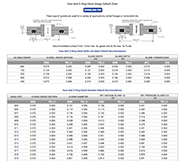
ERIKS standard ORings and load them also into your created design info chemical volume swell (%) cross section diameter (mm) ISO 3601 free Calculate Results Reset calculatorOring groove design considerations and engineering guides for static face seals, metric orings, static dovetail orings, static rodpiston orings and dynamic rodpiston orings Find the right oring groove design and easily order your oring online from theGroove design guide for static oring face seals provides default recommendations on width, depth, diameter and more for basic applications Oring face seals are used in a variety of applications, including bolted flanges or removable lids
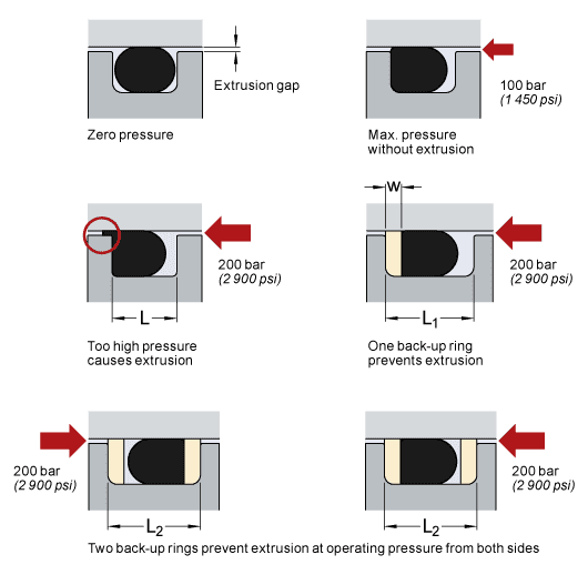
Housing Design And Dimensions Skf Skf
O-ring groove design face seal metric
O-ring groove design face seal metric-Designing the parts of an application where orings will be applied is broadly termed "oring groove design" In order to seal properly the oring has to deform in the application by being compressed and stretched in any number of ways The design of the groove where the oring sits plays a major role in how the oring performs its sealing roleCreated Date AM
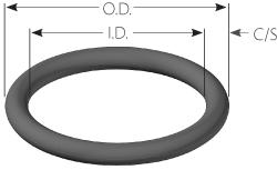


Custom Metric O Rings Metric O Ring Seals Standard Metric O Rings
Phone (800) Fax (510) Face Seal Gland Design Chart Side Wall Angle is to allow for releasing of molded parts Sidewalls of machined parts should be vertical Groove OD (Ho) For Internal Pressure Dimension the groove by it's OD and widthBritish Standard > BSP ORing Seal;American Standard > SAE ORing Boss Awivel;
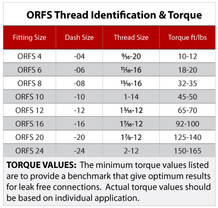
Specifications Met All SealLok Oring Face Seal fittings meet or exceed the strict requirements of SAE J1453 Our SealLok Oring Face Seal fittings with ISO 6149 metric ports also meet ISO Connection 1 Type Various Connection Styles Available Connection 1 Tube Outside Diameter 1/4 to 2 inch, 6 to 50 mmThe Oring calculator tool is intended to form the basis of an oring installation, and assist with selection of oring and hardware dimensions Recommendations are based on available technical information, and are offered as suggestions only, any reliance placed on such information by the user is strictly at the user's riskFace Seal Groove Design (Flange) Dimensions apply to all laterally loaded o'rings in static face seal grooves for both liquid pressure and vacuum applications
METRIC ORING GROOVE DESIGN Contact Us For Assistance Or Samples Click Here and contact us today to receive a free quote or if you have any questions regarding sizing × Dismiss alert Metric oring groove dimensions are listed for the most common metric cross sections with and without backup rings We have included Static, dynamic,One general guideline for good Oring application and design is to maintain a range of % sqeeze on the Oring (~1040% for static and no more than 30% for dynamic) No less than 75% of the seal crosssection should be contained within the groove to ensure the seal does not "roll" or extrude out of the grooveFace type seals are sometimes rectangular in shape These types of seals are often referred to as "racetrack grooves" due to their shape When designing such a seal to receive a standard Oring , the inside corner radii of the groove should be at least three times (ideally six times) the crosssection diameter of the Oring to avoid overstressing the ring or causing corner creases that
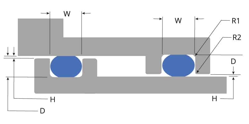


O Ring Groove Design Global O Ring And Seal


O Ring Groove Design Standard As568b Seal Design Inc
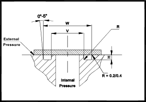
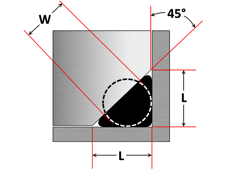
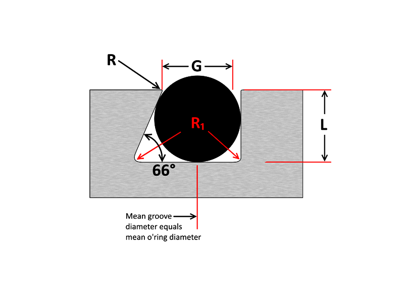
Dovetail and HalfDovetail Grooves It is sometimes necessary to mount an Oring in a face type groove in such a way that it cannot fall out The dovetail groove described in Design Charts 44 and 45 will serve this function This groove is difficult and expensive to machine, and the tolerances are especially criticalDETERMINING ORING CROSS SECTION Face Seal 101 006/ooo GROOVE ÓEPTH z 178 010 —ooo GROOVE IDTH MAXIMUM DISTORTION AND FLEX BETWEEN SEALING SURFACES 007" Á6012 ooo/—060 GROOVE OD 006" 007" 013" 052" 8 210" Quantify all factors that can reduce nominal squeeze on ORing cross section, — Maximum groove depth can vary from4300 Catalog SealLok™ ORing Face Seal Tube Fittings Dimensions and pressures for reference only, subect to change A Fig A1 — Captive Oring Groove (CORG) Cutaway with Parker's trap seal SealLok Introduction The SealLok fitting meets or exceeds the strict requirements of SAE J1453 and ISO It is an Oring face seal type


Custom Metric O Rings Metric O Ring Seals Standard Metric O Rings


Oring Ehandbook
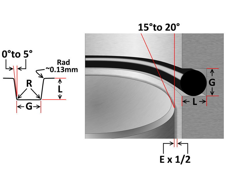
ORing Installation, Design & Specification Gland (Groove) Sizes Static Cylindrical Applications ORing Installation Design & Specification For Dynamic / Reciprocating Applications ORing Installation Compressive Load vs Hardness Chart 070 Diameter ORingThe ERIKS Oring design calculator features the calculation of • oring dimensions for the use in a specific groove • groove dimensions for the use of a specific oring • evaluation of both, any combination of oring and groove for axial seals with inner or outer pressure, piston seals and rod seals A noncircular face seal footprint might also be called a racetrack groove, a wandering groove or a custom plan view When using an Oring, the main design consideration is the corner or smallest radius (shown "r" in diagram) The inside radius should be at least three times the Oring cross sectional diameter


Housing Design And Dimensions Skf Skf
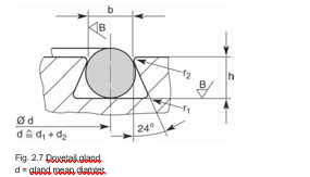


2 Design And Detail Information O Rings Stock O Ring Webshop
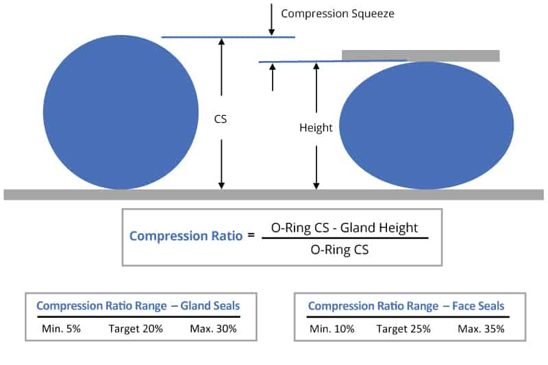
NPSM 60 Cone Seal;ORing Design Considerations What to Know About ORing Squeeze, Stretch, Compression, and More Our oring groove design guides list default oring groove dimensions for the most basic applications and are intended to be used with the following oring groove design considerations to engineer on oring gland to optimize specific application performanceCal drive belts More information, including design criteria on Oring drive belts and their application will be found in ORing Applications, Section III 12 What is an ORing Seal?
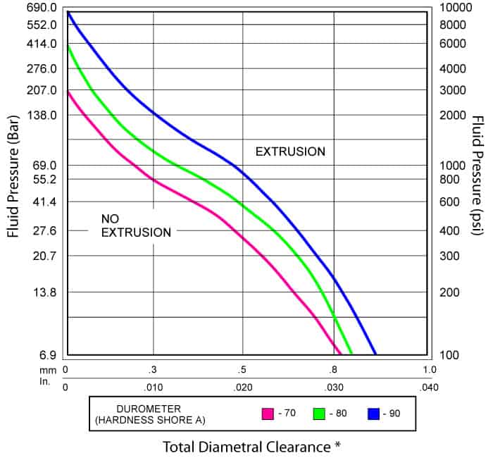


O Ring Groove Design Global O Ring And Seal
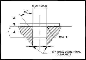


O Ring Seals Roy Mech
SAE 90 Cone Seal; Metric O Ring Face Seal Groove Design History Of The Iso 3601 Series Of Standards For O Rings Fluid As568b Standard O Ring Groove Design Seal Design Inc O Ring Groove Design O Ring Groove Dimensions Mykin Inc Groove Design Gland Design O Ring Groove Gland Design O Ring Seals For Dynamic ApplicationsMetric sized Orings are readily available in the following materials with a $ per size minimum Black Nitrile (BunaN) 70 and Black Viton® 75 Standard sized Black Aflas® 80 and Blue Fluorosilicone 70 Orings are available in 05 weeks Teflon® Encapsulated FEP/PFA Viton® and Silicone Orings are available in 04 weeks


The Different Between O Ring Boss And O Ring Face Sealing Sae Fittings Youtube
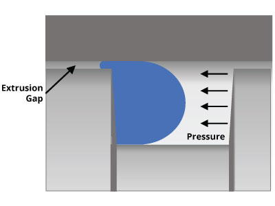


O Ring Groove Design Global O Ring And Seal
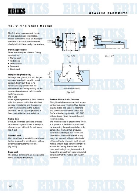
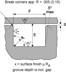
• Corners should be chamfered to limit damage during seal installation ORing Gland Fill % ORing Volume) / (Gland Volume) • Gland volume vs ORing volume • About 25% void space or 75% nominal fill • Need space in groove to allow for volume swell, thermal expansion, and increasing width due to squeeze • Narrower groove for sealingGland Design for Static Application for Orings with Axial Squeeze Surface Finish X groove top and bottom for liquids X = 32 micro inches (08 μm Ra) • Gland Dimensions Static ApplicationFace Seal GlandsMetric W Oring Cross Section E Gland Depth F24 Cone ORing Seal LT 24 Cone ORing Seal HT 24 Cone Multiseal LT 24 Cone Multiseal HT Standpipe Straight;
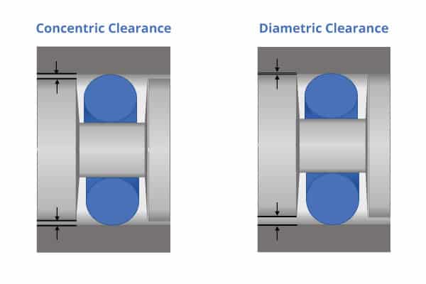


O Ring Groove Design Global O Ring And Seal


O Rings Sealing Australia
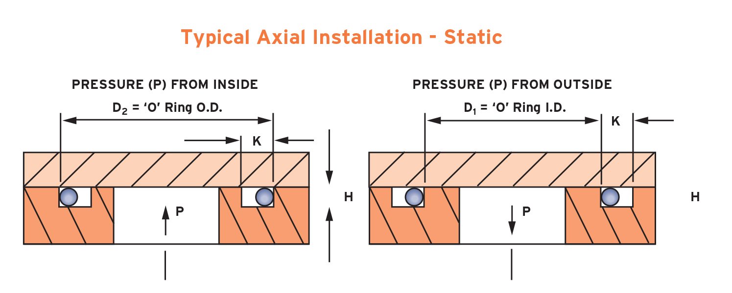
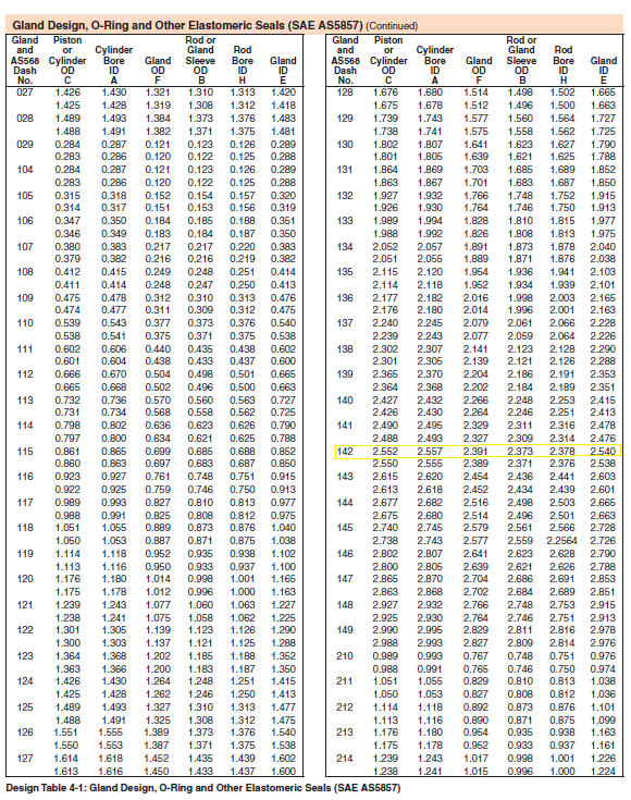
Orings are designed for both static and dynamic applications A properly designed Oring groove allows the Oring to be squeezed diametrically outofround even before the pressure is applied The distortion of the Oring's resilient elastic compound fills the leakage path, thus, creating a sealIn most static applications, a Square Ring will serve as a direct replacement for an oring and generally will perform a highpressure sealing function as well as or better than an oring For more information or to request a quote on Square Rings, please give us a call at or submit the Product Inquiry FormThe oring gland design is very simple for face seals Simply cut out a circular groove into one of the plates and leave the other plate completely flat, the groove will have a square/trapezoidal cross section and the dimensions are conveniently already calculated and laid out in tables in the Parker Oring Handbook


Www Applerubber Com Src Pdf Seal Design Guide Pdf


Metric O Ring Face Seal Groove Design
Industrial Static Seal Glands metric conversion 32√ = 8√ Groove width Design Guide 42 Guide for Design Table 42 410 Parker Hannifi n Corporation • ORing Division 2360 Palumbo Drive, Lexington, KY Gland Dimensions for Industrial ORing Static SealsStatic axial seals are typically used in face seal applications The table on our detailed information page recommends dimensions for static axial (internal pressure) seal glands by AS568A Oring dash numbers Orings serving as face seals in the static axial gland should consider the surface finish of the gland, temperatures and pressureWill also be different if the Oring is sealing a liquid which has a low volume swell on the ring (015% Design Chart 1&3) or if it is sealing a liquid which has a high volume swell on the ring (1525% Design Chart 2&4) It has not been practical to attempt to seal liquids which will swell the Oring


O Ring Groove Design Seal Design Inc


Sealing Methods Adaptall
According to BS4518 the ORing reference number = ORing Inside dia (mm 4 digits 1 decimal place)"" O Ring Section (mm 2 digits 1 decimal place) with the decimal point excluded For example is an Oring of 545mm ID with 30 mm section Surface Texture The surface texture of the surfaces in contact with the Oring seals should not exceedRubber Seals, Sealing Devices & ORing Seal Design AppleParker´s ORing Selector is an engineering tool which offers Oring material and size selection combined in one tool Both are interlinked, thus ensuring the best possible combination of the calculated Oring size and material choice The ORing Selector covers both imperial and metric


O Ring Groove Design Guide Recommendations Allorings Com


O Ring Seals Roy Mech
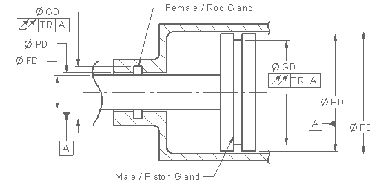
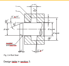
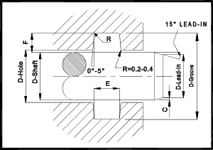
Oring in the smallest possible groove (ie, at the hardware and Oring tolerance stackup) and the smallest possible Oring in the largest possible groove ORing Gland Types and Nomenclature Most static Oring seals can be classified into one of the three arrangements shown below The variable names PistonType Seal FaceType Seal RodType1 Male or Plug the Oring groove is located on a plug which is inserted into the housing or cylinder (fig 123) 2 Female or Tube the Oring groove is located in the housing or cylinder and a tube is installed through the Oring lD (fig 124) Male or Plug Seal design is based on the following factors (refer to fig 123) Bore'O' Ring Guide Introduction The 'O' ring, or toroidal seal, is an exceptionally versatile sealing device Applications, ranging from garden hose couplings to aerospace or oil and gas duties, make it the world's most popular volumeproduced seal 'O' rings offer many benefits to designers, engineers, maintenance staff and plant


Static Face Or Flange O Ring Seals Designs And Gland Dimensions
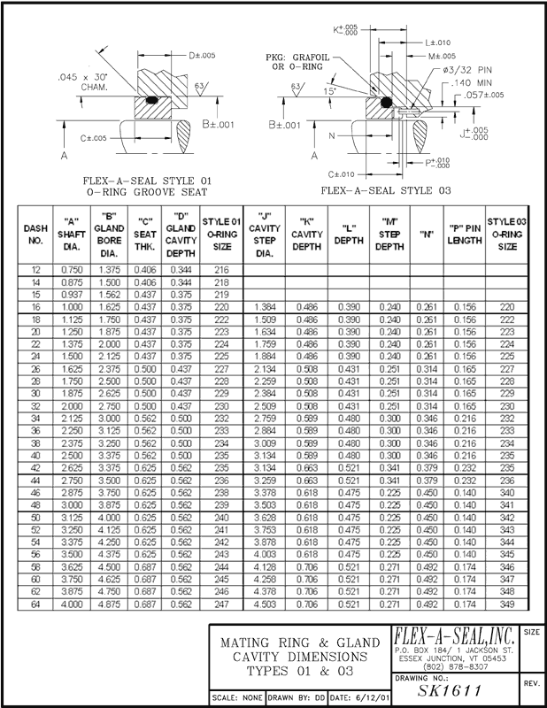


Mechanical Seal Mating Rings Stationary Seats Flexaseal Engineered Seals And Systems
Preliminary Oring Design Considerations An oring is a simple and versatile ring shaped packing or sealing device Having a circular cross section that functions as a seal, in both static and dynamic applications, by being compressed between the mating surfaces comprising the walls of the gland, in which it is installedJIC 74 Cone Seal;Bay Seal Company ORing Reference Guide Bay Seal Company 8 Sealing is our Business!


Seals Eastern O Ring Rod Seal Design Guideline
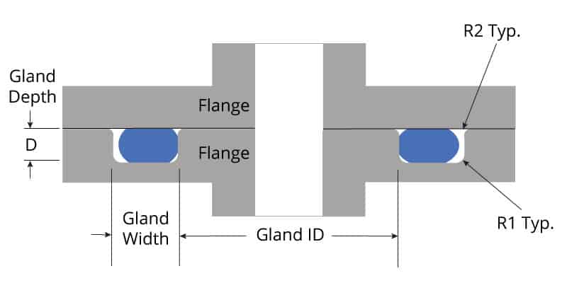


O Ring Groove Design Global O Ring And Seal
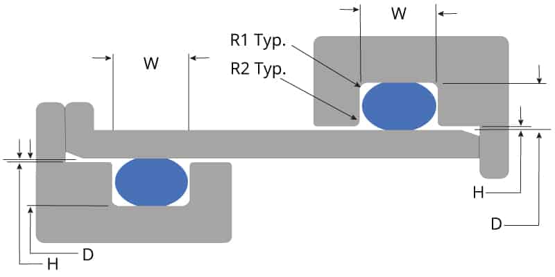
Learn more about Metric ORing Groove Design DOVETAIL ORING GROOVE DESIGN Dovetail grooves are used to hold the Oring inplace on a face seal groove during during assembly and maintenance of equipmentTotal indicator reading between groove and adjacent bearing surface All surfaces and corners must be free of tool marks and scratches ORing groove and dimensions may be calculated as follows (please refer to chart above) Given ExampleOring groove design guides offer default dimensional guidance on the most basic oring groove design applications The best orings are useless without the right groove design which becomes increasingly important the more demanding the application environment Face Seal Flange ORing Groove Design Chart XRing Seals and high


Http Practicalmaintenance Net Wp Content Uploads Working Design Considerations And Maintenance Of O Rings Pdf


Seals And Sealing Equipment Hansa Flex
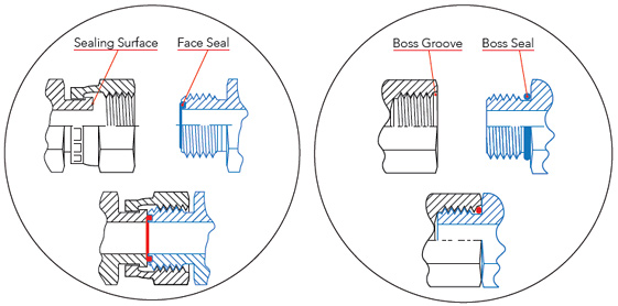
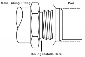
If you are designing a face seal, select the QuadRing® Brand with an inside diameter which will position the QuadRing® Brand on the side of the groove opposite the pressure Click here for more information on face seal groove design Note the QuadRing® Brand inside diameter for the next step Calculate the Seal StretchThe groove design allows the Oring to be retained in the face seal during assembly and maintenance This is beneficial for special applications where the Oring has to be fixed by the groove eg a lid which opens regularly Bosstail The Oring is used for sealing straight thread tube fittings in a bossMetric oring groove designs vary greatly and choosing the right one for your application is important for maximum oring performance This metric oring groove design reference guide will help you find the right radius, backup, pressure and other oring dimensions for basic applications Once you find the exact metric oring you need, you can easily order online from the world's largest oring


Diagram Of The Face Seal Design 1 Seal Ring Flexibly Attached 2 Seal Download Scientific Diagram


Www Hitechseals Com Includes Pdf O Ring Brochure Pdf
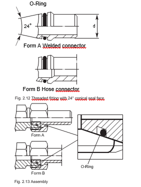
ORing Handbook Parker Hannifin ORing Diision Europe ORing Handbook Parker Hannifin ORing Diision Europe With inhouse compound and design expertise, testing and pro 422 DIN 3865 threaded fitting with 24° seal face forLearn more about Metric ORing Groove Design DOVETAIL GROOVE DESIGN Dovetail grooves are used to hold the Oring inplace on a face seal groove during during assembly and maintenance of equipmentAn Oring seal is used to prevent the loss of a fl uid or gas The seal assembly consists of an elastomer Oring and a gland
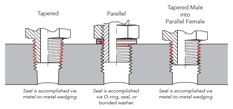


Sealing Methods Adaptall
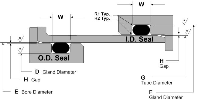


Static O Ring Groove Design A Rod And Piston Glands


2 Design And Detail Information O Rings Stock O Ring Webshop


Http Practicalmaintenance Net Wp Content Uploads Working Design Considerations And Maintenance Of O Rings Pdf


How To Use An O Ring In A Non Circular Groove Pattern


Static Crush Gland Design Static Crush Glands Grooves


O Ring Groove Design Metric Seal Design Inc


Www Applerubber Com Src Pdf Seal Design Guide Pdf


O Ring Info En O Ring Technical handbook 14 eriks nv o Ring technical handbook o Ring gland design new Pdf


O Ring Groove Design Guides Engineering Quick Reference


O Ring Groove Design Sealing Australia


Metric O Ring Face Seal Groove Design
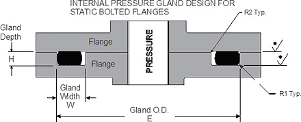


Buy O Ring Groove Dimensions Cheap Online
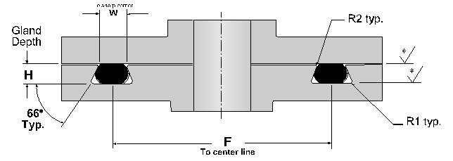


Dovetail O Ring Groove Design Marco Rubber Plastics Custom O Rings Supplier


Oring Ehandbook


Eriks Nv O Ring Technical Handbook
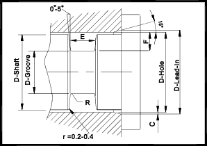


O Ring Seals Roy Mech
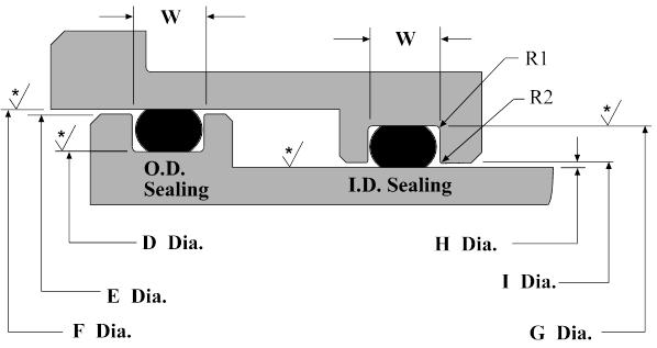


Dynamic O Ring Groove Design Guide A Rod And Piston Glands
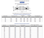


O Ring Groove Design Guides Engineering Quick Reference


Www Trelleborg Com Healthcare Media Tss Media Repository Healthcare And Medical Pdfs O Ring Gb En Pdf Rev Ad60cc2e6bf84a0eaaebeaa9d3 Hash F17dcfe5190b79c85d7f


Metric O Ring Groove Design Reference Guide


O Ring Groove Chart
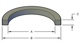


Square Rings Global O Ring And Seal
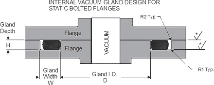


Buy Standard O Ring Groove Dimensions Cheap Online


1


1


Buna O Ring O Ring In Houston And Minneapolis Dichtomatik


Metric O Ring Manufacturer


O Ring Groove Design Standard As568b Seal Design Inc
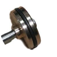


O Ring Groove Design Global O Ring And Seal
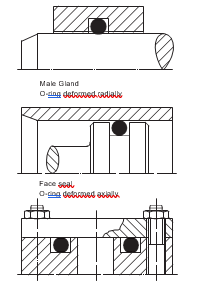


2 Design And Detail Information O Rings Stock O Ring Webshop
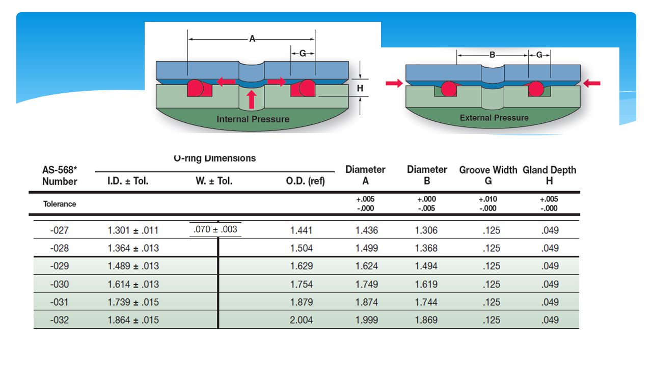


Design Of O Ring Seals Ppt Video Online Download
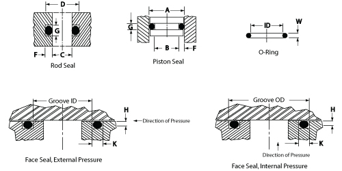


O Ring Groove Design Daemar Inc


O Ring Groove Design Sealing Australia


Straight Thread Tube Fitting O Rings Precision Associates Inc


2 Design And Detail Information O Rings Stock O Ring Webshop


What Is An O Ring Selection Material And Storage Barnwell


O Ring Cross Section O Ring Groove Design Data


O Ring Groove Design Guides Engineering Quick Reference


O Ring Groove Design Sealing Australia


4 Common Mistakes In Designing For An O Ring Axial Face Seal Hot Topics


O Ring Groove Design Dovetail Seal Design Inc


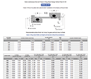
Omniseal Face Seal Gland Dimensions Metric Saint Gobain Performance Plastics Pdf Catalogs Technical Documentation Brochure


Surplus Center


O Ring Groove Design Global O Ring And Seal


Www Hitechseals Com Includes Pdf O Ring Brochure Pdf


Quad Rings All Seals


O Ring Seals Roy Mech


Www Ashtonseals Co Uk Files Mydocs Parker O Ring Handbook Pdf


Proper Installation Of An O Ring Face Seal Gland Parker Hannifin


Eriks Technical Manual O Ring Gland Design Information


O Ring Calculator Ceetak Sealing Solutions


4 Common Mistakes In Designing For An O Ring Axial Face Seal Hot Topics


Static Axial Engineering Design Guide Ace Seal S Gland Design Guide


Groove Design Gland Design O Ring Groove Gland Design


Applications Technology Sealing Elastomers In The Semiconductor Industry Are Used In Hundreds Of Applications Unique Environments Such As Vacuum And Plasma And Demanding Requirements For Contamination Place Great Importance On The


O Ring Groove Design Seal Design Inc


Oring Ehandbook


Great Resource For Designing With O Rings Inventor Tales


Oring Ehandbook


Engineering


Designing Axial Static O Ring Grooves To Industry Standards Grabcad Tutorials


Http Practicalmaintenance Net Wp Content Uploads Working Design Considerations And Maintenance Of O Rings Pdf


Seal Design Store Canada O Ring Groove Design


O Ring Groove Design Global O Ring And Seal


Http Practicalmaintenance Net Wp Content Uploads Working Design Considerations And Maintenance Of O Rings Pdf


Nitrile Nbr 70 Id X Cs Mm Metric Sizes Oring Cs 1 Mm O Ring Seals Buna N 70 Rubber Gasket Rubber Gasket O Ring Sealrubber Sealing Gasket Aliexpress


Engineering Basics Guide To O Rings Eriks Shop Nl


1
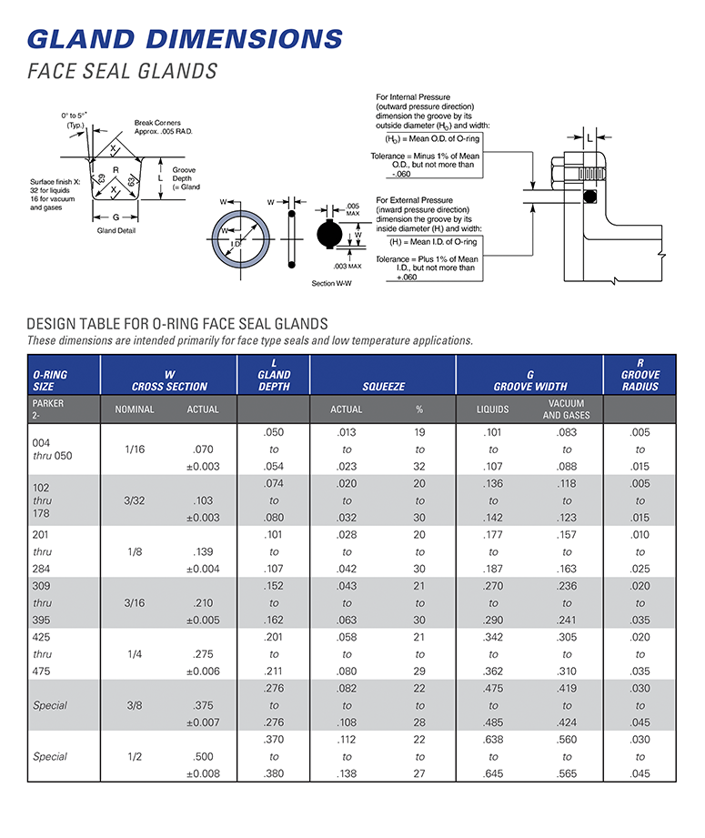


Hydrapak Seals Products O Rings Gland Dimensions


Metric O Ring Face Seal Groove Design


Metric O Ring Groove Design Reference Guide


Static Axial Internal Pressure Gland Groove Design


Buy Standard O Ring Groove Dimensions Cheap Online


Ptfe O Rings Trelleborg Sealing Solutions


3


O Ring Wikipedia


Untitled Document


